
Gears
I am attempting to 3D Print a set of gears and pulleys to expand the range of available speeds and feeds on the lathe.
Most people, when confronted by the gaps in a 9x20 lathe's speed options look to a DC motor and variable speed controller. I intend to make a selection of drive pulleys that can be swapped out to give a wider range with more points in between.
To start with, I intended to use a toothed belt, but slight misalignments between the motor, spindle and tensioner meant the belt kept walking off the pulleys; even when one had been crowned in an effort to prevent it. The quick-change geometry I came up with did work though, so this will be carried through to version 2. There may be a slight revision to add a locking mechanism, as it currently relies of friction.
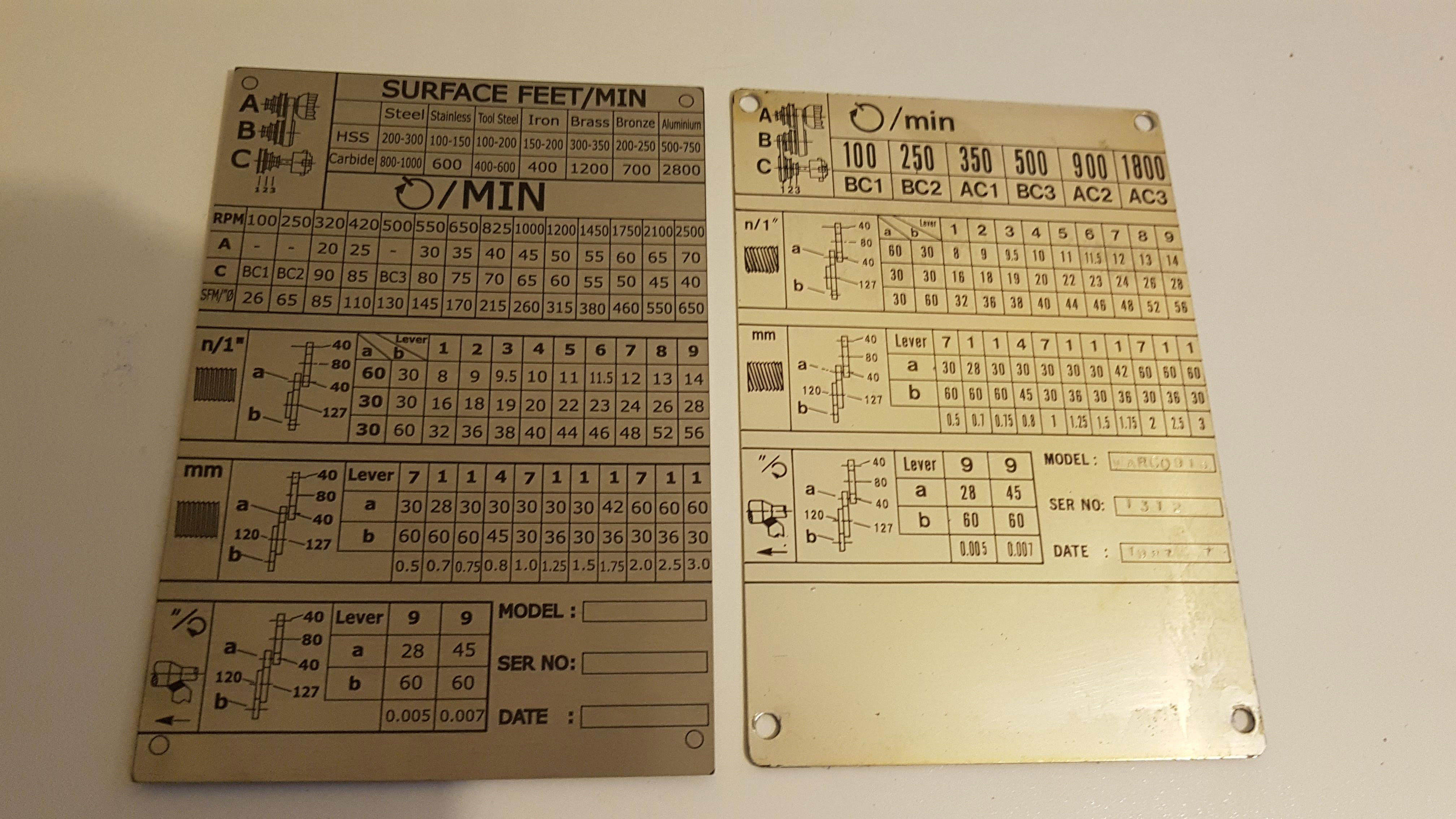
I got slightly ahead of myself, assuming I could make the toothed belt work and designed and had laser etched a new spindle speeds plate, out of stainless steel. I also added a guide surface feet per minute chart, and tied that to the RPM chart by noting the SFPM per inch of diameter. The problem is this plate references the number of teeth on the pulleys; I am planning on changing to a vee belt, as comes standard, so there are no teeth on the pulleys. Each pulley will have to be sized to match the equivalent in teeth, and then marked as such.
 |
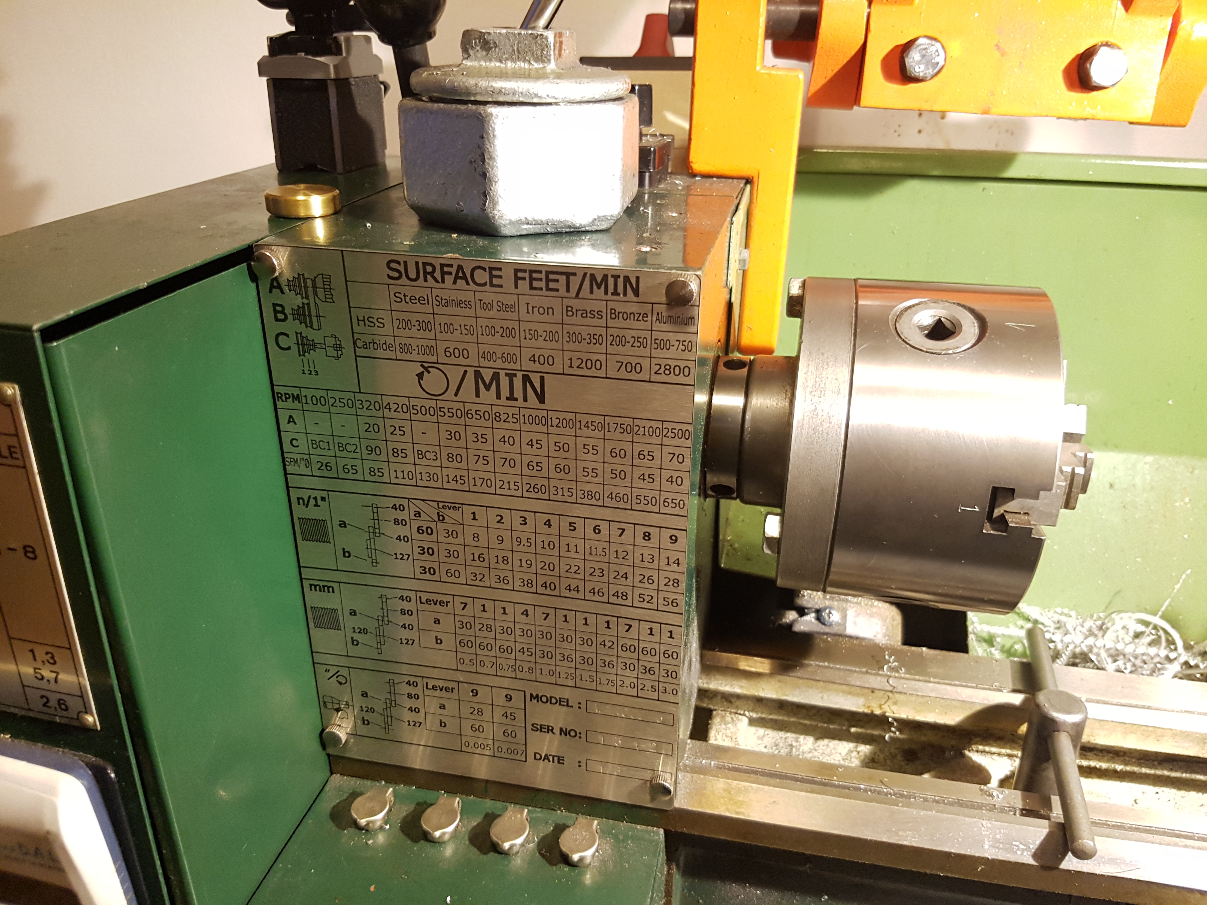 |
| New vs Old | New plate installed on the lathe |
The advantage of running a vee belt, is that no change need be made for running the "back-gear" BC range, and I can fit three speeds to a pulley, like stock. The disadvantage is the printed parts are more difficult to print, and will probably be split into parts for best results - this then requires the use of fasteners.
