
Wiring
The lathe came pretty poorly wired, with the motor rotation switch being used as the on/off switch. This had to change.
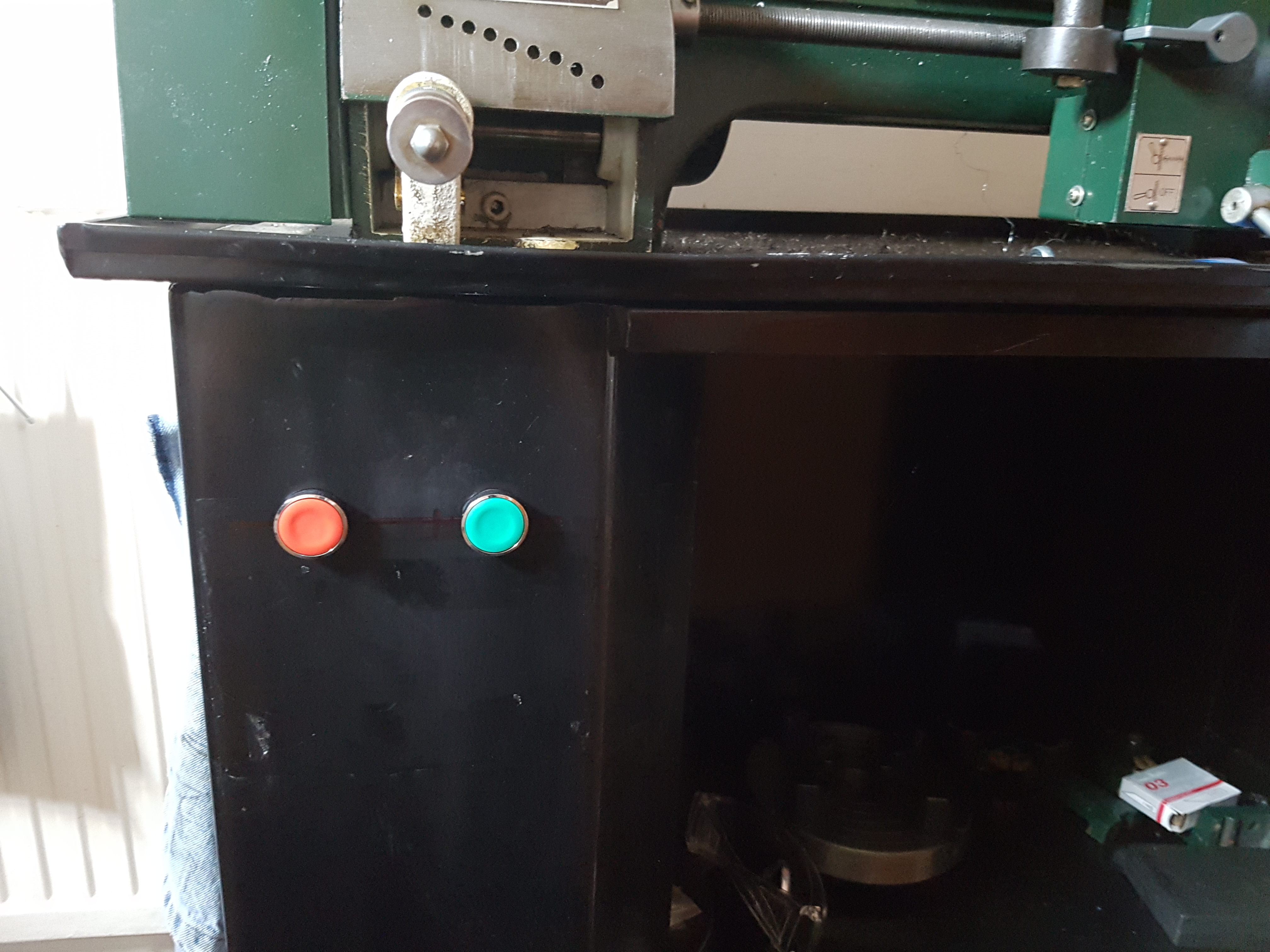
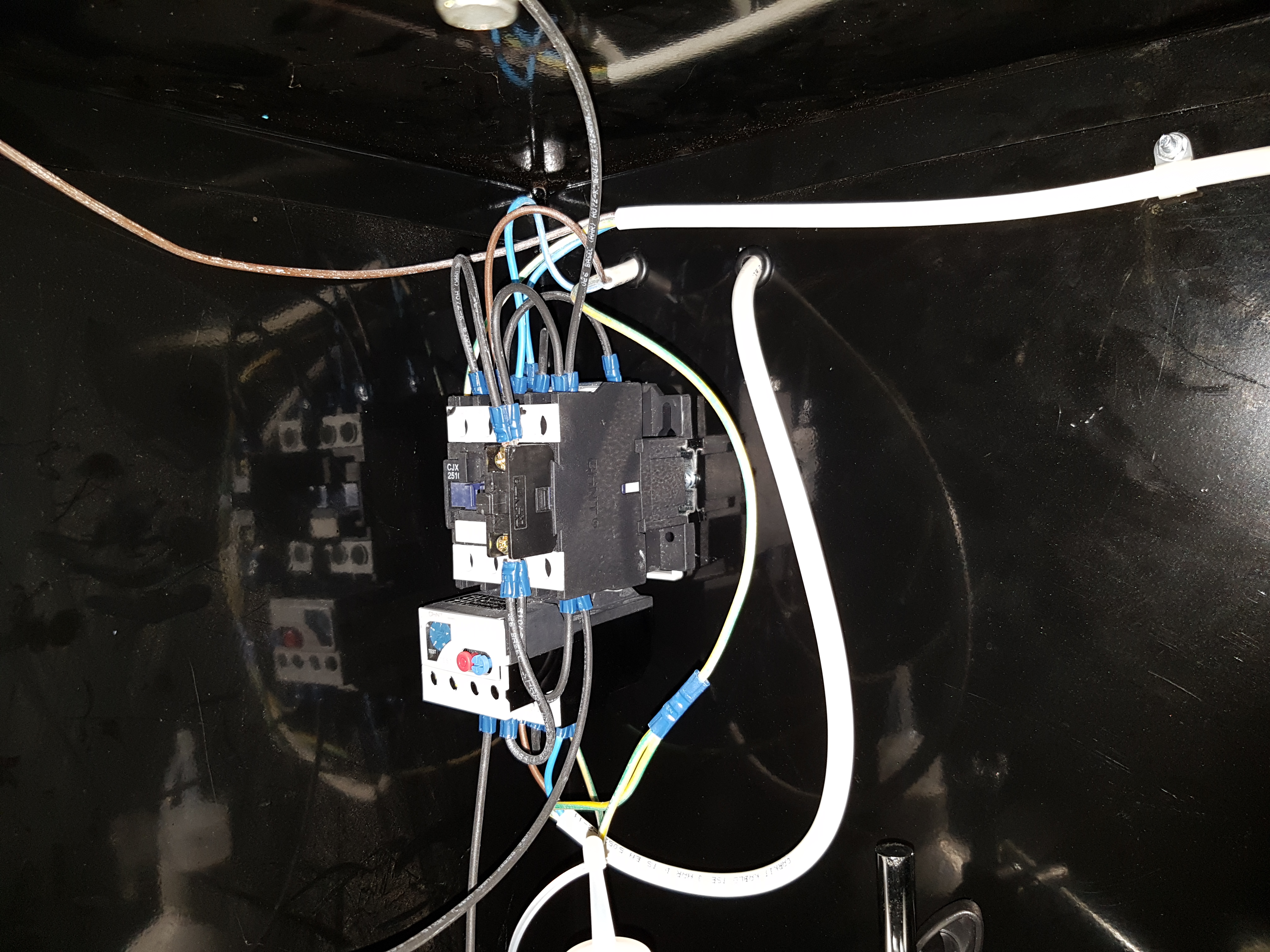
A 3 phase motor contactor is the main switching element. This was used because it came out of the bin; and so cost nothing. A pair of buttons were fit to the stand, and the emergency stop style kick button was also wired in circuit. The contactor is mounted inside the stand, on a piece of DIN rail.
The lathe came with a lock-out switch, but it was damaged. The guts were replaced with those of another salvaged part, and crammed back in the original case.
Recently, the wiring was updated, when a DIN rail 12v PSU was found. A latching switch was added above the motor buttons, and this controls the angle-poise lamp. Previously, this had been running on a small transformer, with the in-line switch dangling behind the lathe.
 |
 |
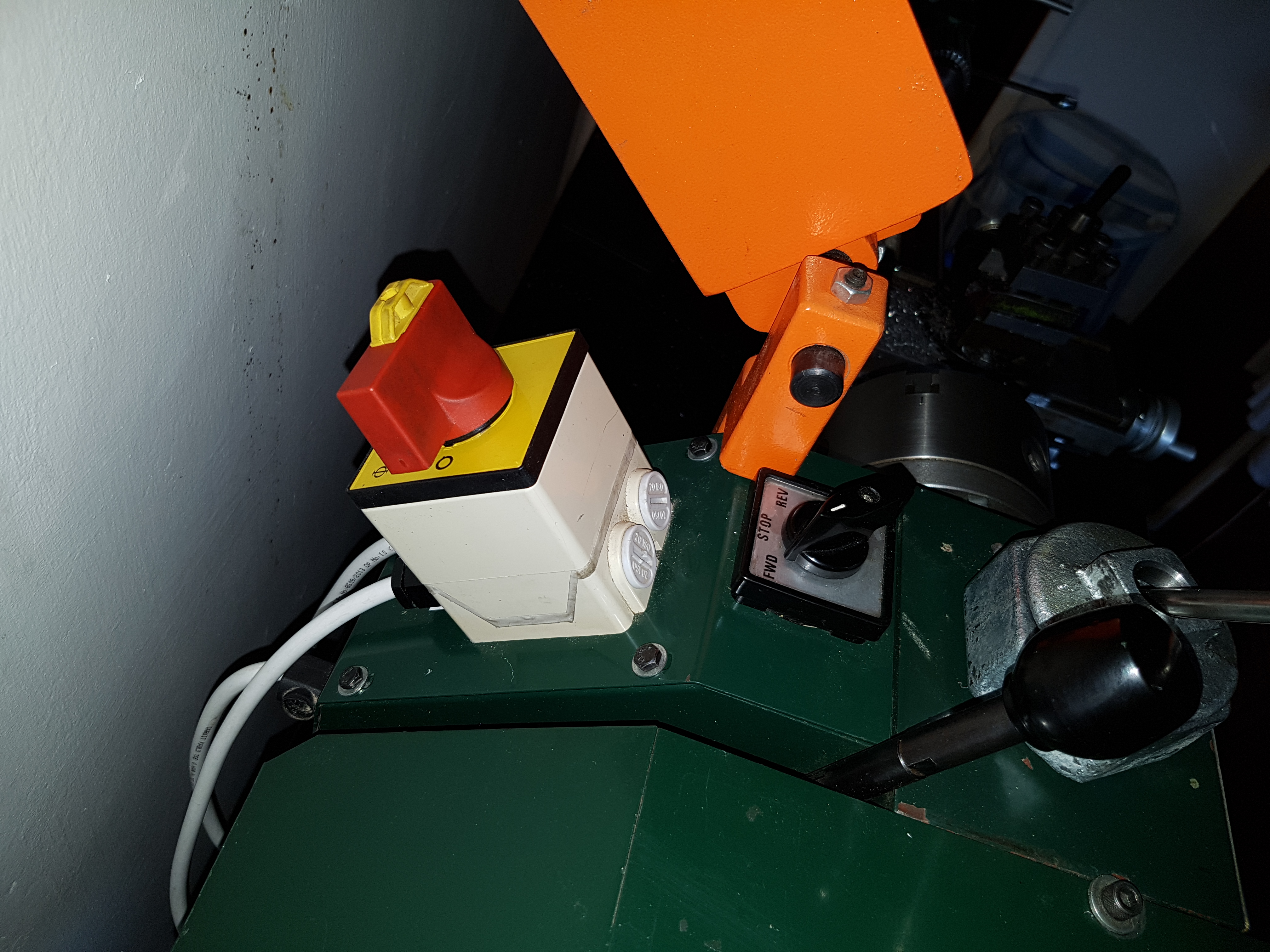 |
| Start Stop Buttons | 3 Phase Contactor | Isolation lock out |
Whilst this set up is overkill for the little motor on these lathes, I feel it is better than switching the motor starting current through the rotary direction selection switch. And with spare phases on the contactor, I could have it switch a milling head in the future; using the direction switch to isolate the lathe motor, and still using the start/stop buttons I'm used to...
All that remains is to make a cover, so the contactor and wires are somewhat shielded.
